

Fully automated complete machining of turbine and special shafts – NILES-SIMMONS develops the new »CENTER AXIS ALIGNMENT« process
Dr.-Ing. Moritz Halle, Dipl.-Ing. Thomas Wächtler, NILES-SIMMONS Industrieanlagen GmbH
The field of application
In highly technical, innovative, and sensitive industrial sectors such as the aerospace industry or the defense and energy sectors, the demands on the production of complex components and the machining of high-strength materials are constantly increasing. In particular, the reduction of error within production processes for highly complex and cost-intensive workpieces is becoming more important with regard to the »cost-per-part« and the accuracies to be achieved.
To meet these requirements, NILES-SIMMONS has developed the new fully automated and patented machining and measuring process of »CENTER AXS ALIGNMENT« specifically for the machining of turbine shafts. This process enables the complete machining of complicated, deep-hole drilled shaft-shaped workpieces including all in-process measurements without manual operator intervention.
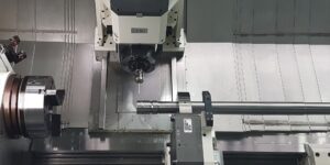
Image 1 – Complete Machining of Turbine Shafts without Operator Intervention
The aim of the machining process is to adapt the outer contour of the workpiece exactly to the inner contour in order to achieve a uniform wall thickness of the workpiece along its axis. The process is applicable to all electrically conductive materials such as simple steels, but also for super alloys or nickel-based alloys such as Inconel 718. In addition to the machining of turbine shafts, it also applies to other deep-hole drilled workpieces up to two meters in length.
The machine configuration
The new process is executed on a NILES-SIMMONS N30MC machining center with a center distance of 4500 mm and a swing diameter of 780 mm; the machine has been purposely configured for this machining operation. The specific equipment of the machine includes a main spindle, a turning-milling unit, a lowerable tailstock, two steady rest slides with one steady rest and one damping unit, and a boring bar slide.
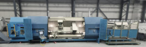
Image 2 – Process »CENTER AXIS ALIGNMENT« on a NILES-SIMMONS Machining Center N30MC
Furthermore, independent tool magazines are available for both the boring bar slide and the turning-milling unit. The magazine for the multi-axis turning-milling unit, placed on the main spindle side, can be equipped with up to 144 tools. For the boring bar slide, up to 16 positions are available in an additional boring bar magazine on the tailstock side. System boring bars up to two meters long, driven boring bars, static boring bars, static boring bars with controllable cutting edge, measuring lances, or a cartridge with drive and chuck function can be used.
With this configuration, and particularly by using the lowerable tailstock, all types of turbine shafts currently available on the market can be machined in different lengths on one machine. Even particularly long components can be easily machined, especially due to this option, without having to choose a machine with a larger footprint.
Furthermore, all cutting technologies such as turning, milling, drilling, gear hobbing, tapping, thread milling, thread turning, reaming, spindles, internal machining with indexable inserts, power skiving, 5‑axis milling, and deep-hole drilling up to 2000 mm depth can be mapped in a process-reliable manner. In addition, the machine integrates the automated touch probe and optical measurement of tools as well as the automatic touch probing of the workpiece. With that, it is possible to achieve accuracies less than 5µm for the turning and milling processes. Due to the integration of all necessary technologies in one machine, the automated tooling, and the use of complex measuring technologies, an unattended complete machining process is applied in a process-reliable manner.
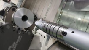
Image 3 – Internal Machining with System Boring Bar with adjustable Cutting Edge
To achieve increased temperature stability and to ensure the accuracy required by the customer despite temperature fluctuations, we use a liquid-cooled special concrete machine bed. In addition, the machining centers have dampening and vibration-reducing components such as FE-optimized slide geometries, hydraulically clamped components of the workpiece support components such as tailstock and steady rest slide, dampening surfaces in machining direction, and roller guides of the machining axes in size 45/55.
To ensure clear and simple operation of the machine, we use a Siemens OP19 with an additional touch screen for process monitoring.
The patented measuring process
The key element of this innovative process is the new measuring process for determining the optimal shaft center axis. This process was developed and patented by NILES-SIMMONS and is based on the application of the eddy current measuring principle which measures the distance between the eddy current sensor and the workpiece.
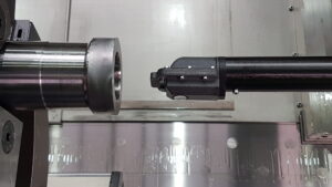
Image 4 – Eddy Current Sensor for Determining the Optimal Workpiece Center Axis
This principle belongs to the non-contact inductive measuring principles, which can also measure through non-conductive materials without having any influence on the measuring result. The method is therefore ideally suited for use in harsh industrial environments. Dust, dirt, and oil do not influence the measurement. Temperature fluctuations are offset by an efficient temperature compensation.
Due to the fully automated measurement value recording, the process can be carried out without any operator – from the first clamping of the workpiece until it is clamped in its new center.
A special eddy current sensor including evaluation unit from µEpsilon is used here, which has been calibrated to the workpiece-specific properties. This sensor covers a measuring range of up to 9 mm with a resolution of less than one micrometer.
The applied sensor is mounted at the tip of a 2000 mm long carbon lance, which is integrated in an exchangeable modular measuring cassette. Thus, the sensor is positioned and moved via the machine axes of the boring bar unit in the working area of the machine within the deep hole drilled workpiece. Once the sensor is positioned, the distances between the sensor and the workpiece can be measured with precision at any angle by rotating the workpiece.
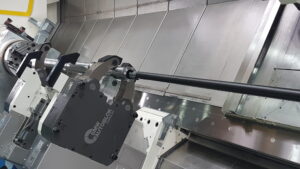
Image 5 – Carbon Measuring Lance in the »CENTER AXIS ALIGNMENT« Process
The center point of the considered diameter is calculated from these measured data. Along the longitudinal axis of the workpiece, any number of center points can be determined with this method, which represent the current course of the bore. Knowing the course of the bore, the ideal new course of the center axis is calculated from the calculated center points. This center axis then forms the basis for machining the new clamping seats of the workpiece to accommodate it in the new clamping operation.
This automated process minimizes the deviation of the outer contour line from the inner contour line, thus ensuring a uniform wall thickness of the shaft along its axis.
The Value
The main advantage of »CENTER AXIS ALIGNMENT« is the fully automated measurement, alignment, and machining of deep-hole drilled workpieces without operator intervention.
All steps necessary for the process run fully automatically within programmed process limits. Faulty manual operations or error-prone manual measuring processes, which were necessary in conventional processes, are eliminated. This makes it possible to reduce the production of scrap parts to a minimum and to improve the quality of the workpieces significantly. Unsuitable raw parts are identified and rejected at the beginning of the process.
The integration of all technologies and measuring processes in one machine allows cycle times to be shortened and logistics and handling processes to be reduced.
The measuring method is immune to environmental influences such as temperature fluctuations or foreign substances and can be used flexibly for a wide range of materials. Due to the modular design of the NILES machines, different types of workpieces can be processed and in-process measurements taken on the same machine. This creates maximum flexibility for the customer.
The process has already been successfully integrated into turbine shaft production on the market.
DOWNLOAD
Download Whitepaper as PDF
CONTACT
SALES – TEAM
NILES-SIMMONS Industrieanlagen GmbH
Tel.: +49 371 – 802 204
Mail: sales.nsi@nshgroup.com